Here's what started it all:
http://lufdesign.blogspot.com/2008/01/saverclip.html
via http://www.yankodesign.com/2008/01/14/saver-clip-shames-your-electricity-usage/
via http://i.gizmodo.com/344778/saverclip-offers-unique-new-way-of-measuring-energy-consumption
Local copy (archived on terrible-ideas.com)
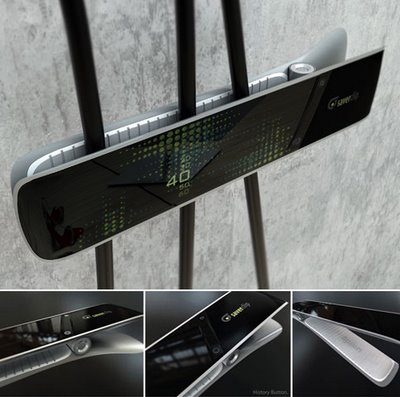
Saverclip induce people not to waste electricity by showing Electromagnetic Fields (which is detected by safer clip) on its display, in that way people can recognize the amount of electricity being wasted.
 s
s
Safer (sic) clip is charged by electromagnetic fields, that come from the electric wire plug, and Its (sic) display shows the amount of the power needed for the each devices. When the devices are off, safer (sic) clip displays standby-power being wasted and induce them to stop wasting it.
Here's the problem: this is not how you'd measure electical usage. It is not possible, practical or even a solution to a problem that hasn't been solved yet. As far as I can tell, some "designer" made a couple renders of this design and posted it without any consideration of the physics involved.
Or, as quoted by people smarter than me:
nimblesquirrel's comment on Gizmodo
To be honest, I doubt it would work. Yes, you can use induction to measure the current in a single conductor. It is how clamp multimeters work. [en.wikipedia.org]
But when more than one conductor is passed through the clamp, the measured current is a vector sum of what is passing through. If it was a normal single phase cable (two conductors + earth), the sum would be zero. Only current imbalances would be detected, and this is exactly how a Residual Current Circuit Breaker works.
On top of that, in order to measure current by induction, the conductor (or conductors) need to be surrounded by a loop of ferromagnetic material (which acts as a transformer core. That doesn't appear to be the case with this clip design.
It would be a nice concept, if it could happen, but this just seems to be the case of a designer who really didn't have much clue about the underlying physics of what he was designing.
And..
floatingbones' comment on Yanko Design:
1. To measure current, you need a clamp meter. The Wikipedia article on this technology is pretty good: http://en.wikipedia.org/wiki/Clamp_meter . Besides the meter, you need the power and ground lines broken out.
2. The other gotcha with measuring AC current is whether or not you have a true RMS meter. If there is a nice smooth sinusoidal wave on the line, a non-RMS meter will be sufficient. However, if the curve isn’t smooth, a non-RMS meter will be very inaccurate.
3. In the power/neutral/ground 3-wire configuration, the ground line is no carrying any current (unless the device is badly broken). This picture shows current going through all 3 wires. That leads one to conclude that the picture has been photoshopped or it’s very tiny 3-phase wires (very unlikely).
4. If you do want to measure current, there are the kill-a-watt devices which you plug between the outlet and the device. They’ll measure wattage over time. The kill-a-watt EZ device will extrapolate and compute how much $$$ a device will consume over a year.